Energy Model
ThermalZone
Component
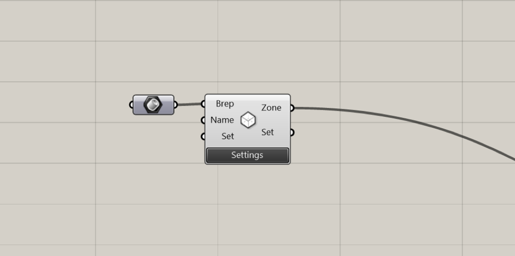
The Zone component is the starting point for creating the key elements in a thermal simulation, the thermal zone. The “BREP” input requires you to provide a Brep geometry, which represents a room or a group of rooms with similar thermal properties (Limitation: only poly-surfaces consisting of planar surfaces are supported). If you provide a list of Breps the component will produce a list of thermal zones. The second input “NAME” allows you to provide a specific name to a space in order to facilitate the results interpretation later on. This is optional. If you don’t provide a name Archsim will assign “UNZ” and a number to your zone. The third input “SET” is also optional and should only be used by advanced users. It allows you to override the settings that come from the GUI with a string (in case you do not like the GUI or you would like to be able to parametrically set some of the inputs). This string has to be formatted just like the text that is output under “SET”. You can either provide this text via a text panel or use the advanced settings components to do so in a more “Grasshopperesque” fashion.

Screen shot of an Archsim zone component on the Grasshopper canvas
Settings
The loads tab lets you define internal heat sources such as people, equipment and artificial lights. Lights are hard wired to a dimming control in the GUI. People and Equipment loads can be folded with an availability schedule. The conditioning tab gives you control over the space conditioning in a specific zone. You can control set-point temperatures, availability schedules and capacity of your heating and cooling system. Further mechanical ventilation can be specified. Under the ventilation tab, you can specify natural ventilation and infiltration of your zone. “Scheduled Ventilation” can be used when air exchange rates of a zone known, e.g. form a computational fluid dynamics (CFD) simulation. The “Natural Ventilation” section can be used to calculate wind and buoyancy driven airflow in a zone. The underlying equations are given below. The “Materials” tab defines the constructions used for the zone. Archsim automatically categorizes the Brep sub-surfaces into elements such as “roof”, “slab to ground”, “internal wall” etc. The constructions that you can pick form are predefined in the library. Custom materials, constructions as well as schedules can be defined in the library editor available under the library button or via grasshopper components. The later workflow is described in a later section.
Internal Loads
Conditioning
Ventilation
Domestic hot water
Constructions
Windows
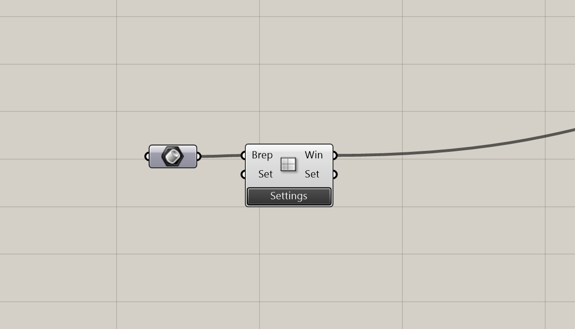
The window component attaches glazing materials, dynamic shading systems as well as natural ventilation specific information to a surface. Under the settings button you can select the window type as interior or exterior window. Under shading system you can activate a movable shading device that is triggered by the set-point radiation. E.g. if the set-point is set to 180watt/m2 then the shading device is activated whenever this amount of radiation is reached or exceeded on the facade where the window is placed.
 Window component on the Grasshopper canvas
Zone Connectivity Network
Component
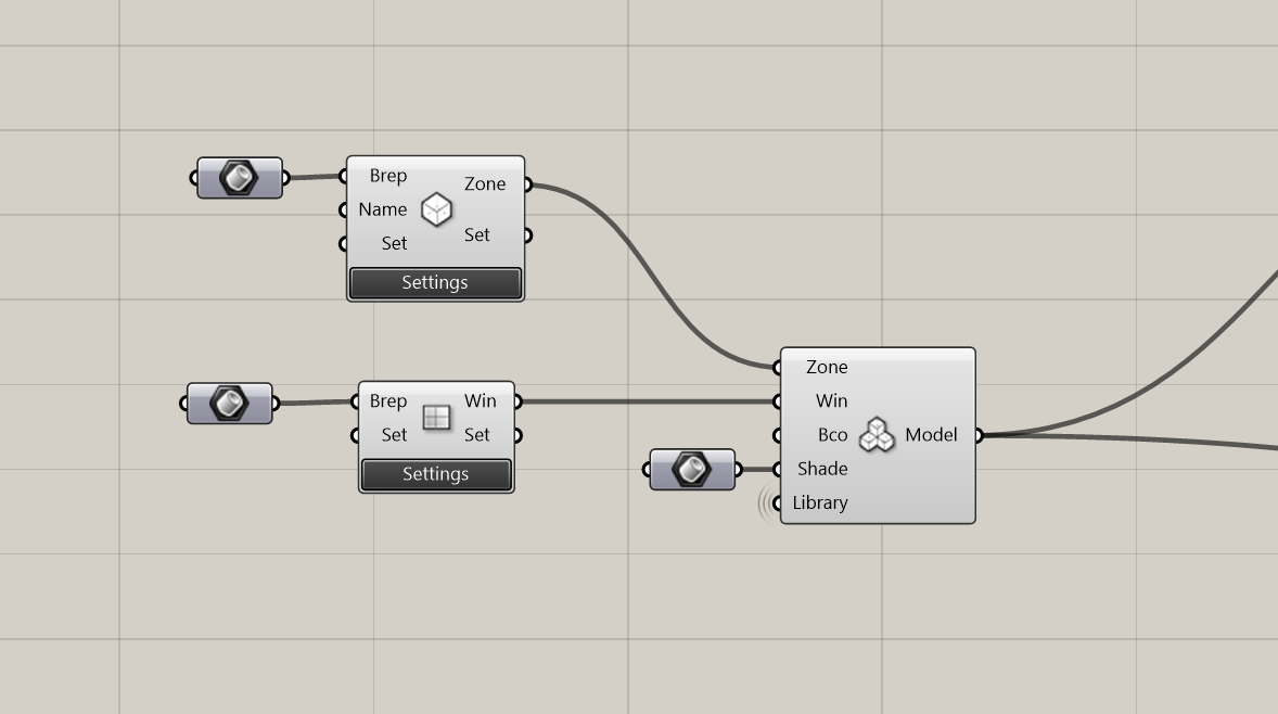
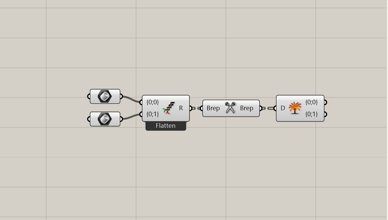
This component takes multiple zones windows and shading/boundary surfaces and combines them in one thermal model. The component searches all zones for adjacency of their sub-faces to establish a connectivity network and distributes the provided windows to its parent surfaces. Adjacency is detected by finding surfaces that overlap exactly (adjacent surfaces must be congruent). If a model contains touching surfaces that are not congruent, Archsim will not be able to recognize the adjacency. The solution is to subdivide the surfaces. This can be done manually within Rhino or automatically with the Intersector component. The Intersector work flow can be implemented as a pre-processing step and the geometry is then baked into Rhino layers. For large models automatic surface intersection can be a costly operation and might take a couple of seconds to minutes. An example workflow with a data tree input structure is shown below. The tree structure is maintained by the Intersector and hence makes it easy to retrieve branches of the intersected geometry.

Zone and window component connecting to the Networker component

Setting up the geometry for a multi-zone model with the Intersector component
Multi-Zone
The use of multi-zone models is driven by the idea to further spatially resolve micro- climatic and functional differences within buildings such as space orientation and programmatic use. Such differences have significant impact on the load behavior of a space and thus also on the specifications for an HVAC system that serves it [Bobenhausen, 1994]. To simplify the simulation and system layout, multiple rooms may be joined together into one zone if they share similar load profiles. However, lumping spaces of different character together in one zone can lead to significant load under-predictions [Smith et al., 2011]. For example, a localized heat surplus that may occur during the winter near a south-facing façade may be absorbed by a space to the north that is underserved by solar gains. Consequently, the predicted energy demand according to the one-zone thermal model would be dampened due to load cancellation compared to a spatially resolved multi-zone model. In early design, when the room layouts that would provide the basis for thermal zoning are yet unknown, ASHRAE 90.1 Appendix G prescribes a zoning methodology stating that a floor should be divided into core and perimeter regions. The perimeter is defined as the space along the facade with a depth of five meters. Further, perimeter spaces with more than one orientation should be subdivided proportionally. The leftover region in the center of the floor forms the core [ANSI/ASHRAE/IESNA, 2013].